• You are viewing the forum as a Guest, please login (you can use your Facebook, Twitter, Google or Microsoft account to login) or register using this link: Log in or Sign Up

LED light unit failed

Joined
26 Feb 2013
Messages
3,412
Hi all,

I have custom made LEDs that just happened to fail all of a sudden. The guy that made them has disappeared and I have no idea if I can fix them and how.

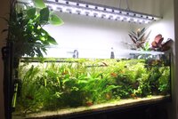
They are three separate strips of LEDs installed on aluminium bar as heat sink, each bar has with its own driver and plug so not sure why they all failed about the same time plus/minus a couple of weeks.

The LEDs he used are High Power 3W CREE XM-L's, 15 LEDs on each bar, connected to this driver model on the link below.

12-18*3W LED External power supply (AC85-265V) [JNY-L3060W-B] - $9.99 : Wayjun Technology, Focus on the production and development of LED

The symptoms are: one bar blinks, sometimes works fine. Two of the bars switch off completely, sometimes if I let them off for a while they may start and work for a couple of hours.

Has anyone got any idea what I can do?
 
Is that driver from the link going to be ok specifications wise for one strip. The strips are 15x3W=45W each?
No, not powerful enough, you need obviously need at least 45W 650mA driver. Can't see one at the moment that jumps out from RS. You can of course split each bar into say 25W @ 650mA, but then wiring and no of drivers becomes large (and expensive).

Are you sure they are Cree XM-L LED's (the XM-L's I found are 10W ?) and how are they protected from damp and water from the tank ? That may be your issue of course.

Also 3 x 45W LED is a humungous amount of light, I assume that is over a suitably humungous tank ?
 
p6c5.jpg
Thanks Ian.

Yes, the lights are Cree XM-Ls.

I am totally not sure what the issue is, not an electrician either. There doesn't seem to be a circuit break because they do switch on from time to time just when they want to. One bar blinks but then it will work eventually if I switch it off for a few min. Here is a picture of the light unit, each strip is on separate plug and driver
 

Attachments

  • p6c5.jpg
    p6c5.jpg
    352 KB · Views: 230
I made my own led light unit and have had similar problems.

In my case the unit was getting damp and individual leds were failing the result was all other leds were lit but very dim and sometimes flickering.
 
Here you go, 700mA 45W driver, from OSRAM.

4008321664433 - OSRAM - LED DRIVER, 45W, 0.7A, 120V | Farnell UK

Switch settable at 700mA, 500mA & 350mA but interestingly has a variable mode, put about 2-11V from potentiometer into control pin to vary the current. Handy for algae control....

I ended up buying this one Ian after all three bars gave up working for good unfortunately. My poor plants are gone ape blahblahblahblah, melting, couldn't buy a driver for two weeks.....
Now a few stupid questions.

I bought the driver you recommended to test it first with the intention to buy two more for the other strips if it solves the problem and works fine.
There are dip switches and it's currently set to 700mA, would this be the correct one?
I've no idea what potentiometer is, is it for dimming?
I connected the 3 input wires from the mains to the driver on L/N and ground and output from driver to LEDs is red to positive and brown/black wire to negative connected to the driver. There's a third wire that's insulated with the red and black but it was not connected to anything originally and the LEDs light up without it. It's yellow/green like ground wire colour. I just left it insulated?
It's working now :):), Lights on...... I am just afraid I did something wrong. I am total newbie when it comes to these things :(...

Thank you so much for your help
 
Yes set the DIP switches to 700mA (DIP1 off, DIP2 On). Obviously setting to 500mA or 350mA will be not as bright.

I would wire up as below:
LedDriver1_zpsd61614d8.png

I suspect the yellow/green wire, you talk about, is an earth wire. You need to check & confirm. The metal work of your LED bracket MUST be earthed, as shown above in my Green/Yellow connection. If there is a fault, eg live wire comes loose, LED driver catastrophically fails and the live mains ends up being connected to the metalwork, the fuse(s) would blow disconnecting the mains. If you didn't have the earth it would present a serious potential shock hazard upon a fault. In this case hope that mains is on a RCD protected circuit, which is not really the way to protect yourself.

Interestingly with the LED drivers you have if you set the DIP switches to both off, you can control the brightness via a potentiometer. eg http://uk.farnell.com/te-connectivity-citec/23esa473mmf50nf/potentiometer-lin-47k/dp/350096

This is my interpretation. You could connect to more than one driver module by connecting one +12Vset wire to the potentiometer from first module and Vset and GNDset wires to all modules. This would control all modules.
Brightness_zps6758047a.png

This is from the data sheet if you want to control only one module.
Brightness2_zps57d535a4.png
 
Cheers Ian. This was very helpful.
There is a green/yellow wire on both cables the one from the mains to the led(which I've connected along with L/N) and the one from the driver to the lights. This one I haven't connected, only the red and black.
The original driver was connected only via red/black from the driver to lights without ground and same from mains to driver, the ground was not connected at all on both sides, just cut off.

So should I connect ground on both sides? I think the metal work of the LED is not earthed. The cable comes out from one side and I opened the LED metal frame to check what cables come out of it. There's just a red and black cable coming out connected to the black and red on the round cable which has the third green/yellow cable inside it but it's not connected to anything at all.
As I mentioned above the ground wire was not connected at all to or from the old driver as well so should I connect it anyway?

Thanks again. I won't switch on the lights till I am sure it's right or you'll never here from me again :D:D
The ports of the driver are here:
http://www.osram.com/media/resource/hires/340448/219286/OPTOTRONIC OT 45220-240700 LTCS.pdf

On the wiring diagram on page 3 it shows the connections the new driver has. I've connected mains black/red to L/N and green/yellow (1 wire) to PE/FE ground
Then from the driver to the LED the red and black are connected to the bottom red and black connectors on the driver(wiring diagram page 3) which are indicated as LED + and -. If the ground wire is to be connected too on this side, which port on the driver is the ground output to LED unit?(though as I mentioned the LED unit has just red/black connected/coming out of it, and no ground wire)
 
Last edited:
The LED driver earth is labelled PE (protective earth) and has an earth symbol on it and page 6 of above says you should connect it.

You should also connect any "touchable metal" with electrics on to earth as well. That is what I suspect your third green/yellow wire is/was for, for connecting to the metal of the LED mount.
 
The LED driver earth is labelled PE (protective earth) and has an earth symbol on it and page 6 of above says you should connect it.

I've connected the green/earth from mains to the LED driver (PE/earth port).

You should also connect any "touchable metal" with electrics on to earth as well. That is what I suspect your third green/yellow wire is/was for, for connecting to the metal of the LED mount.

Should I connect the green/earth wire from driver to LEDs although the ground wire isn't connected to anything on the LED side? If I have to connect it, first which output(to LED from driver) port on the driver is the 2nd ground connection? And then should it be connected if there green/ground wire is not connected,just insulated inside the cable and it isn't touching the metal frame/LED side part?

Sorry for the mountain of questions, just not sure and I am useless as you can see.
 
I've connected the green/earth from mains to the LED driver (PE/earth port).
Correct.

Ideally you need a connection, like below, my green/yellow wire, connecting the metal of your LED frame to mains earth, this sounds like what the third yellow/green wire in you LED connecting cable was intended for, but never connected. Connect it to the metal of the frame by a bolt for instance.

LedDriver1_zpsd61614d8.png

However, as this is not a product on sale and if you trust the isolation of the LED driver and your mains sockets are on RCD's you could leave the earthing of metal out :confused: Bit surprised it wasn't earthed in first place.
 
An RCD, residual current device, detects the mismatch between the current in the live wire and current in the neutral wire. If there is a difference (usually 30mA) it means the "electricity is leaking" away somewhere.

If you touched your LED mounting bracket that was accidentally connected to live due to a fault, the RCD would detect the current mismatch due to the current going through you and cut the power before it did you any death type things....hopefully. Most modern houses will have RCD's on the mains and even more modern have RCD's on the lighting circuits as well. If your house hasn't got RCD's (or modern RCBO = RCD + overcurrent in one device) all you aquarium electrics should be on an RCD in cause of "incident", especially as water in involved.

As for surge protectors, known in computer trade as "chocolate teapots". They designed to stop mains surges damaging delicate equipment. Couple of issues, proper surge protectors that work cost serious money and in UK actually have very good surge free mains supply. Our super UPS/surge suppressor at work once recorded a couple of spikes of 270V and drops to 225V but in the 6 odd years of logging zilch really.

This is proper suppressor that works, but cost £100.
1843212-40.jpg

This is a home cheapy mains suppressor.
chocolate-teapot1.jpg


Here is a chocolate teapot.
2792-500x500.jpg
 
Hey Ian, one of the light strips failed again. This time it isn't the driver as I connected the driver to the third strip and it's working on it.

I noticed a couple of days ago that one of the leds on the very end of the failed strip was kind of dimmer than the rest. Today it just failed to turn on. It was working yesterday. I tested with both "working" drivers and the entire strip won't light. Could it be a break in the circuit if one led light fails then all of them fail to work. I've no idea how this guy has connected them inside the light unit itself.
 
You are using Cree LEDs so doubtful it has failed, though of course if your previous driver had damaged it then maybe.

I would therefore suspect wiring fault. You should just be able to bypass the failed LED with a temporary piece of wire and see if the rest of the string works. You will have to use your Sherlock Holmes head to fault find. You have started already and proved the driver is working.
 
Back
Top