• You are viewing the forum as a Guest, please login (you can use your Facebook, Twitter, Google or Microsoft account to login) or register using this link: Log in or Sign Up

Co2 and tanks with sumps

Boshk

Member
Joined
15 Jan 2018
Messages
32
Location
Hong Kong
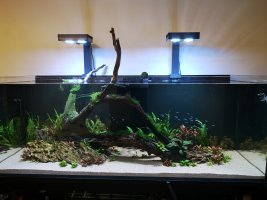
Hi guys, I converted my reef tank with sump to Freshwater. There are lots of pros with it but I'm finding some cons to, mainly related to co2.
PROS:
1) Zero film on surface, the overflow takes care of it.
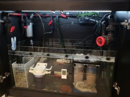
2) Sump hides all my heaters, media, filters, reactors, sponges etc
3) water change from the sump instead of DT

BUT...
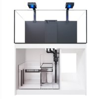
I'm finding there is too much gassing off due to the way the reef tanks with sumps are designed, too much turbulent water. My DC return pump is already set to the lowest setting.
My drop checker only goes from blue to light blue only.
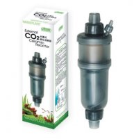
I had my diffuser placed in the usual position inside the display tank (on right side) but I could see the micro bubbles float then follow the current go down the overflow and into the sump, where I am assuming its gassed off. Not much of the bubbles reached the left side. I increased the co2 but the tank ended up like 'fizzy bubble show'

I'm trying something different now with the Diffuser in the sump placed right next to the Return pump. I was hoping the Return pump would act like a co2 reactor pulling in the bubbles and 'chopping' it smaller and hoping the gas will dissolve as it returns to the display.
Results are only slightly better, finer bubbles which reaches both sides of the tank but they still float up quite quickly since the flow setting is at its lowest.

Recommendation on how I can improve the dissolve rate? less gassing? more efficient use of co2?
 
This is the tank....I put a Y loc-line nozzle at the top so the co2 bubbles can reach both sides
 

Attachments

  • 425nw2.jpg
    425nw2.jpg
    44.1 KB · Views: 257
I put my co2 into the return pump and have no trouble getting enough co2 into the tank to drop it more than 1 ph, i just put a cigarette filter into end of co2 tube to break up the bubbles and it works perfectly.
 
You are doing the right thing placing the diffuser near the return pump inlet - there is no reason to have it in tank. Better still add a reactor to the return pipework if you want better dissolution and less CO2 usage.

What is your tank volume and your current bubble rate?
 
thanks for the replies. Volume is 500L, current bubble rate is around 60-70/min...pH doesn't drop by 1, average around 0.4 drop, but if I increase the bubble rate, the tank ends up like 7up fizzy show and I start seeing a lot of wasted co2 from the Return pump chamber because water level is low-ish
Maybe I should try a reactor whether its DIY (like Foxfish's) or one of those Ista ones.
Any suggestion or experience with them?
 
Last edited:
mixed reviews on these guys, some say they leak all over the place, some say its best thing ever......
 

Attachments

  • ista co2.jpg
    ista co2.jpg
    38.5 KB · Views: 180
  • ista-max-mix-co2-reactor-l-voor-aquaria-tot-1000-liter_3.png_April-26-2020-1046am.png
    ista-max-mix-co2-reactor-l-voor-aquaria-tot-1000-liter_3.png_April-26-2020-1046am.png
    328.4 KB · Views: 234
Watching this thread with interest as I’m also running a sump on my planted tanks. Intending to move my diffuser to the DC intake but not keen on potential micro bubbles.

I’m installing a new tank and planning on an inline diffuser or using an old ozone reactor as a co2 reactor,

I assume you have your return outlets pointed down into the tank away from the surface?
Yes, point downwards probably about 20degrees. The microbubbles just reaches the sides but a lot end up floating up.
The DC pump is rated at 4500L/hr at 4ft head height, 5 settings Lo to Hi, currently on lowest.....so I'm assuming its around 1000L/hr now.

Its sort of a dilemma with freshwater, prefer calm, non turbulent flow and definitely no wave like motions, whereas Reef tank...stick in wavemakers, crank return pump up to 80%+, more turnover of water the better.
I could crank it up so I push the microbubble down further but then water turnover is higher, more downward flow into sump=more turbulent water=more gassing....
 
Hi, i think @zeus is your man here. Check his Olympus Calling journal.

That said, couple of things:
  • while its not that sensible to compare bubbles per second rates between tanks, 1bps seems very low for such a large tank. On my 200ltr its impossible to count the bubbles, it's just a stream.
  • you could try removing the diffuser and sticking the co2 tube directly into the intake of your pump. I do this and means you do not lose any co2 in the return pump chamber.
  • a small power head in the tank would help distribution. But it is un sightly.
  • If you really hate bubbles in the tank then I suspect you'll have a lot of trial and error finding an atomiser/reactor set up that works for you. Not tried myself, but seems a common story on the forum.

K
 
As @Kezzab says irrespective of bubble size differences between tanks, 1bps is way too low on a 500 litre tank. I'm sure @Zeus. will pop up when he wakes up, and post his infamous bubble rate video clip, but to give you an idea, on my previous 60 litre I was at around 2.5bps, on my new 100 litre the bubble are to fast to count by eye. if you are losing too much CO2 out of the sump water surface you could consider a better diffuser like the Twinstar Rio - I would have though that, placed right next to the pump inlet would not result in any bubbles at the sump surface.

You are actually doing well to get a 0.4pH drop with just 1bps, especially with a sump, which is quite surprising especially as you are running at quite a low tank turnover - are you getting that pH drop in all areas of the tank? Depending on your layout, you may find you run into distribution issues, getting the CO2 enriched water to all necessary areas of the tank. Again, in my 100 litre tank the Oase 850 - which is rated at 1500 lph, but likely pushes out far less in use, and even less still as I've strapped a 20" CO2 reactor after it - has to be supplemented with a AI Nero 3 to get sufficient distribution.

In terms of reactors, those Ista ones haven't got particularly good reputations - and that was enough to make me moved to a DIY one. I went for a 20" filter housing, modified with an internal acrylic tube and a JBL ProFlora diffuser before it - that ensures I get almost complete dissolution of CO2 before it enters the tank, with the exception of the tiniest micro-bubbles which are indistinguishable from O2 bubbles being released by the plants.

EDIT: I have added some details of my reactor to Nigels thread here: DIY Barr's venturi design reactor build
 
Last edited:
I'm going to be facing the same issue once I get my reefer 350 up and running. I've considered a few options, but one is to have a split CO2 distribution: One reactor in the sump inflow, so the water that comes in already gets some CO2 into it, and a bazooka/diffusor inside a plastic bottle with the opening of the bottle leading to the inflow of the return pump, like in foxfish's drawing. This would hopefully result in more dissolved co2. Zeus's suggestion to use 2 seperate CO2 systems for this could work even better, since you could turn off one once you hit the right CO2 level, and use the remaining one to keep that level. I'd originally planned to just use one regulator with 2 outlets (CO2art elite). See Two complete CO2 System vs One with multi output regulator for more info. I'm also going to cut some perspex to size to cover most of the sump with, in the hope that helps a bit as well. I'm following this thread with interest to see what else comes by that could help :)
 
I'm going to be facing the same issue once I get my reefer 350 up and running. I've considered a few options, but one is to have a split CO2 distribution: One reactor in the sump inflow, so the water that comes in already gets some CO2 into it, and a bazooka/diffusor inside a plastic bottle with the opening of the bottle leading to the inflow of the return pump, like in foxfish's drawing. This would hopefully result in more dissolved co2. Zeus's suggestion to use 2 seperate CO2 systems for this could work even better, since you could turn off one once you hit the right CO2 level, and use the remaining one to keep that level. I'd originally planned to just use one regulator with 2 outlets (CO2art elite). See Two complete CO2 System vs One with multi output regulator for more info. I'm also going to cut some perspex to size to cover most of the sump with, in the hope that helps a bit as well. I'm following this thread with interest to see what else comes by that could help :)

I went though this thought process when I was planning a sump set-up. I decided, with two separate return pumps, it would be easier to have a separate reactor loop with its own pump - drawing water from where it enters the sump chamber, running ot through the CO2 reactor, and then returning it to the area close to the return pump inlets.
 
I went though this thought process when I was planning a sump set-up. I decided, with two separate return pumps, it would be easier to have a separate reactor loop with its own pump - drawing water from where it enters the sump chamber, running ot through the CO2 reactor, and then returning it to the area close to the return pump inlets.
Thanks! Even more to contemplate :D I think I have a small pump lying around somewhere. And I have a spare inline diffusor too. Its becoming more and more complex too though XD
 
Thanks! Even more to contemplate :D I think I have a small pump lying around somewhere. And I have a spare inline diffusor too. Its becoming more and more complex too though XD

Sometimes setup has to be complex to make maintenance simple I find. My thoughts with the separate CO2 loop, is I could always pull it out to modify, clean, change etc, without even touching the main plumbing.
 
As @Kezzab says irrespective of bubble size differences between tanks, 1bps is way too low on a 500 litre tank. I'm sure @Zeus. will pop up when he wakes up, and post his infamous bubble rate video clip, but to give you an idea, on my previous 60 litre I was at around 2.5bps, on my new 100 litre the bubble are to fast to count by eye. if you are losing too much CO2 out of the sump water surface you could consider a better diffuser like the Twinstar Rio - I would have though that, placed right next to the pump inlet would not result in any bubbles at the sump surface.

You are actually doing well to get a 0.4pH drop with just 1bps, especially with a sump, which is quite surprising especially as you are running at quite a low tank turnover - are you getting that pH drop in all areas of the tank? Depending on your layout, you may find you run into distribution issues, getting the CO2 enriched water to all necessary areas of the tank. Again, in my 100 litre tank the Oase 850 - which is rated at 1500 lph, but likely pushes out far less in use, and even less still as I've strapped a 20" CO2 reactor after it - has to be supplemented with a AI Nero 3 to get sufficient distribution.

In terms of reactors, those Ista ones haven't got particularly good reputations - and that was enough to make me moved to a DIY one. I went for a 20" filter housing, modified with an internal acrylic tube and a JBL ProFlora diffuser before it - that ensures I get almost complete dissolution of CO2 before it enters the tank, with the exception of the tiniest micro-bubbles which are indistinguishable from O2 bubbles being released by the plants.

EDIT: I have added some details of my reactor to Nigels thread here: DIY Barr's venturi design reactor build
thanks. I will try increasing the bubble rate and take more accurate readings on pH. The probe is actually inside the sump, usually I see it around 7.2 in the morning, during the day its 6.9, so not quite 0.4 drop.

The distribution problem did come into thought but I honestly don't know how to deal with that, especially in a Red Sea tank where the Overflow box is in the middle. When it was a reef tank, I had 1 powerhead and a wavemaker Gyre on each side, return pump cranked up to 60%...........now its just the Return pump at the lowest setting. I'm a bit worried about 'stagnant' areas

I'll take a look at the 10 or 20" DIY reactors, maybe I can source some materials here and make one.
 
I went though this thought process when I was planning a sump set-up. I decided, with two separate return pumps, it would be easier to have a separate reactor loop with its own pump - drawing water from where it enters the sump chamber, running ot through the CO2 reactor, and then returning it to the area close to the return pump inlets.
Mine is similar at the moment.
1st Return pump (Varios-6) just for tank turnover....sump to display.
2nd pump (Varios4) placed in sump as well, runs a UV, a Chiller, Carbon reactor and 2 spare ball valves (closed) I would plumb the co2 reactor to 1 of these ball valves.

Here is the tank and sump, you can actually see the bubbles left and right side, upper 1/3 of tank
 

Attachments

  • IMG_20201210_191308.jpg
    IMG_20201210_191308.jpg
    3.2 MB · Views: 244
  • IMG_20201210_191259.jpg
    IMG_20201210_191259.jpg
    2.7 MB · Views: 264
I get through a 2KG FE in about 100 days for my 180l tank with a green approaching yellow drop checker. So that's 20gr per day, 0.11gr per litre per day.

So for 500l you are looking at 55gr CO2 per day (I have mine on 8 hours).

So weigh your CO2 bottle before CO2 on and when it is off and see what your consumption rate is. I suspect way less than 55gr per day.....
 
Mine is similar at the moment.
1st Return pump (Varios-6) just for tank turnover....sump to display.
2nd pump (Varios4) placed in sump as well, runs a UV, a Chiller, Carbon reactor and 2 spare ball valves (closed) I would plumb the co2 reactor to 1 of these ball valves.

Here is the tank and sump, you can actually see the bubbles left and right side, upper 1/3 of tank

Nice looking tank!

Seems like you are all set up ready to add a reactor, so it should be fairly straight forward for you to add.

Your distribution pattern should be good also given you have an island layout - the two outlets should direct the flow around both sides with water being drawn back over the island. I would say though, the fact that bubbles are rising so soon after leaving the outlet pipes, that you have your pump turned down too low. Do you get any movement in the leaves on those plants at the front, in front of the rocks? If not, I would turn your pump until you see a tiny bit of movement in those leaves, then you know you have enough flow around the island. You may need to angle the outlets down a couple more degrees to achieve that also.
 
Back
Top