
Epiphyte
Member
Bit of background for this project. I like making things more complicated than perhaps necessary, purely for the joy of making things. I love creating and coming up with solutions to things that aren't really problems, just because it either looks good or teaches me something new. I'll start off with the rescape before describing the rest of the project on a second post.
I recently pulled this tank down because I was bored of it. Growth was explosive and I struggled to keep on top of trimming some of the faster growers meaning the hardscape was never really visible. Here's the last photo of the tank I took, probably about 6 weeks before I stripped it down.

For those of whom have seen George Farmer's video showing Tai Strietman's 1500p, they that massive piece of Java Fern in the tank now lives on in in Tai's scape, it was enormous in my 90p, but hillariously disappears in the 150cm long tank.

The carpet grew beautifully since the above photos, and I got a good 5 chunks of MC carpet this size from the tank. Not bad from 6 pots of Tropica 1-2-Grow.

I organised a trip up to Aquarium Gardens for some hardscape inspiration and a good chat with Dave, Tai and George. For someone who is a bit of an "average" scaper, it also gives me a great opportunity to use brains far more capable than mine to come up with a good layout. As always it's a good time with great people at Aquarium Gardens.

In the giant bins of wood I found possibly one of the best single bits of wood for a rescape. It wasn't cheap at £75, but in my opinion it was worth it. I have no idea what wood type it is, but it looks fantastic. I had some WIO "Jade Stone" that I used in my previous scape that I wanted to reuse, Dave kindly allowing me to bring my own supplies into the dojo. A bit of time, consultation with the aforementioned aquascaping pros, and this is the layout I finalised on. The concept was to have a main island, a sub island with a "stream" of MC wrapping around the islands. I think this layout would look better with sand, but sand is more effort when it needs syphoned out and replaced and I am lazy.

Back home, tank cleaned, with the Kings coronation in the background it was time to get started turning this blank canvas into something special. I also swapped out the WIO Bamboo lights I had on test from Tai to the WIO Slim light, just to see how it looked.

I decided to, on advice from Dave, top my old Tropica soil with some new substrate. The price difference between Tropica and ADA is minimal these days and ADA comes with root tabs. I needed some so it was a no brainer to go ADA this time around. In go the root tabs. If you can't tell I like order and uniformity

I've not used ADA Amazonia V2 before and it has a different colour from Tropica so I kept the tropica in the middle and made sure the visible soil would all be ADA. Back home of course it never goes back together as well as it does in the shop, no matter the reference photos you take, but I think I got it approximately right.

WIO Jade Stone in place, wood glued down using the substrate and superglue.

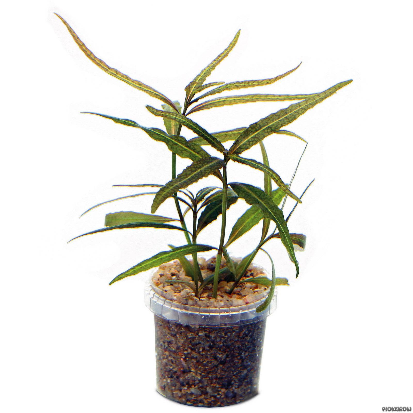
First plant in is this one. Can't remember it's name I'm afraid but Tai said it would look good so I took his word for it and bought 2 pots!

Next was a huge lump of S. Repens from my old tank, split up and planted around to bridge the MC carpet into the longer plants. This is one of about 4 bunches of this size.

Top down, you can see roughly how it's working out

Then, all of this Monte Carlo needed to work it's way in. I actually didn't get it all in, I just had too much of it.

I then forgot to take any more photos, but a mixture of stems in the back (Rotala H'ra, Myriophyllum Guyana and another Myriophyllum species that I don't know the name of, cuttings courtesy of Tai again) were planted and the tank then filled.

Overall, quite happy with the result, but naturally it looks a bit tatty on day 1. Here it is 8 days later:

11 days after flooding:

And last pic of the tank, taken today, 22 days after the rescape (today). I also added some Rotala Bonsai in the tank as it's a particular favourite of mine, though it's not particularly visible. Yes I realise a cabinet door is off in this photo, more of why that is coming up shortly...

It's certainly working it's way to needing its first trim. The H'ra has grown to the surface but I've left it a little longer than I normally would so I can make sure the roots are 100% bedded in before I disrupt the plants. I'm going to do a water change this week and give them a trim, maybe leave the MC a few more weeks before doing the same.
For the "facts" about the tank:
It's an Oase Scaperline 90, filter is the Biomaster 600 Thermo. The filter is brimmed with Seachem Matrix and a massive bag of Seachem Purigen (around 500ml). There isn't even a fraction of a tint to the water, it's gin clear, which isn't a surprise with amount of purigen. The filter has had years of running so the tank had a strong bacterial colony from day 1. I've swapped to orange sponges in the pre-filter and modified the pre-filter "tube" with about 3-4x the amount of holes it comes with as stock. The pre-filter, whilst very convenient, is the Oase's biggest downfall in my opinion, it restricts flow so badly that it doesn't take a lot to cause air issues within the filter, but that's a rant for another thread. Temperature is set to 22-23 degrees.
Stocking is light, About 15 rummynose, 15 green raspbora and a few others. I plan to add a few more as time goes on, maybe a nice nannacara pair, my fav tropical fish (as you can tell by my profile picture!)
Light is currently a WIO Slim RGB but I will probably change that soon. Not sure what to as I'm not 100% on the colour rendition on the WIO, it's a little too purple for my liking. Photo period is 8hrs at 100% and has been since day 1.
I use RO water, remineralised to a TDS value of 120. I have always used Saltyshimp, but I've just swapped out to APT Sky. I've had great success with APT products so I thought I'd give it a go.
I'm injecting CO2 but rather than the inline injection I've always used, I've decided to try a CO2 stone, my thoughts on this and why I changed my injection method can be found here. In addition I use an Intaqo CO2 controller and dosing pumps. I've been using it for about a year and love it! So nice to be able to see what the CO2 is doing in the tank rather than guessing what to do based on how a drop checker will change colour in a few hours. I do still keep a drop checker on the tank whilst I fine tune pH levels in the tank, but once I've got that set I'll move it around the back out of view.
Inlet and outlet pipes are Aquario Neo with the "bell" outlet. In addition I've also got the Oase surface skimmer in the tank, hopefully I'll get this removed now I'm no longer getting random plants floating as they've all rooted. The skimmer on the Neo pipes is more than powerful enough to keep a film free surface, I think they're a great product!
Dosing wise I actually haven't dosed this tank yet in the 3 weeks, but I'll start probably today or tomorrow as I've finalised my dosing pumps... more to come of this later. I do however use APT Zero as my ferts of choice. In my opinion lean dosing ferts is the way forward. I dose just enough (6ml per day), the plants grow beautifully, the colours are rich and since I swapped from a richer dosing regime my algae has gone from a bit of a mess to non-existent (aside of BBA, but that's CO2 related, see above).
So 3 weeks in to the new scape, plants are growing well, zero algae to be seen, BBA has all gone from the buce, I'm honestly over the moon with the tank so far.
Next post I'm going to go in to my cabinet as that's where the real fun is for me. I'll probably post it tonight or tomorrow, but hopefully it'll be interesting for you all to see, it's a little different to the norm!
I recently pulled this tank down because I was bored of it. Growth was explosive and I struggled to keep on top of trimming some of the faster growers meaning the hardscape was never really visible. Here's the last photo of the tank I took, probably about 6 weeks before I stripped it down.
For those of whom have seen George Farmer's video showing Tai Strietman's 1500p, they that massive piece of Java Fern in the tank now lives on in in Tai's scape, it was enormous in my 90p, but hillariously disappears in the 150cm long tank.
The carpet grew beautifully since the above photos, and I got a good 5 chunks of MC carpet this size from the tank. Not bad from 6 pots of Tropica 1-2-Grow.
I organised a trip up to Aquarium Gardens for some hardscape inspiration and a good chat with Dave, Tai and George. For someone who is a bit of an "average" scaper, it also gives me a great opportunity to use brains far more capable than mine to come up with a good layout. As always it's a good time with great people at Aquarium Gardens.
In the giant bins of wood I found possibly one of the best single bits of wood for a rescape. It wasn't cheap at £75, but in my opinion it was worth it. I have no idea what wood type it is, but it looks fantastic. I had some WIO "Jade Stone" that I used in my previous scape that I wanted to reuse, Dave kindly allowing me to bring my own supplies into the dojo. A bit of time, consultation with the aforementioned aquascaping pros, and this is the layout I finalised on. The concept was to have a main island, a sub island with a "stream" of MC wrapping around the islands. I think this layout would look better with sand, but sand is more effort when it needs syphoned out and replaced and I am lazy.
Back home, tank cleaned, with the Kings coronation in the background it was time to get started turning this blank canvas into something special. I also swapped out the WIO Bamboo lights I had on test from Tai to the WIO Slim light, just to see how it looked.
I decided to, on advice from Dave, top my old Tropica soil with some new substrate. The price difference between Tropica and ADA is minimal these days and ADA comes with root tabs. I needed some so it was a no brainer to go ADA this time around. In go the root tabs. If you can't tell I like order and uniformity
I've not used ADA Amazonia V2 before and it has a different colour from Tropica so I kept the tropica in the middle and made sure the visible soil would all be ADA. Back home of course it never goes back together as well as it does in the shop, no matter the reference photos you take, but I think I got it approximately right.
WIO Jade Stone in place, wood glued down using the substrate and superglue.
First plant in is this one. Can't remember it's name I'm afraid but Tai said it would look good so I took his word for it and bought 2 pots!
Next was a huge lump of S. Repens from my old tank, split up and planted around to bridge the MC carpet into the longer plants. This is one of about 4 bunches of this size.
Top down, you can see roughly how it's working out
Then, all of this Monte Carlo needed to work it's way in. I actually didn't get it all in, I just had too much of it.
I then forgot to take any more photos, but a mixture of stems in the back (Rotala H'ra, Myriophyllum Guyana and another Myriophyllum species that I don't know the name of, cuttings courtesy of Tai again) were planted and the tank then filled.
Overall, quite happy with the result, but naturally it looks a bit tatty on day 1. Here it is 8 days later:
11 days after flooding:
And last pic of the tank, taken today, 22 days after the rescape (today). I also added some Rotala Bonsai in the tank as it's a particular favourite of mine, though it's not particularly visible. Yes I realise a cabinet door is off in this photo, more of why that is coming up shortly...
It's certainly working it's way to needing its first trim. The H'ra has grown to the surface but I've left it a little longer than I normally would so I can make sure the roots are 100% bedded in before I disrupt the plants. I'm going to do a water change this week and give them a trim, maybe leave the MC a few more weeks before doing the same.
For the "facts" about the tank:
It's an Oase Scaperline 90, filter is the Biomaster 600 Thermo. The filter is brimmed with Seachem Matrix and a massive bag of Seachem Purigen (around 500ml). There isn't even a fraction of a tint to the water, it's gin clear, which isn't a surprise with amount of purigen. The filter has had years of running so the tank had a strong bacterial colony from day 1. I've swapped to orange sponges in the pre-filter and modified the pre-filter "tube" with about 3-4x the amount of holes it comes with as stock. The pre-filter, whilst very convenient, is the Oase's biggest downfall in my opinion, it restricts flow so badly that it doesn't take a lot to cause air issues within the filter, but that's a rant for another thread. Temperature is set to 22-23 degrees.
Stocking is light, About 15 rummynose, 15 green raspbora and a few others. I plan to add a few more as time goes on, maybe a nice nannacara pair, my fav tropical fish (as you can tell by my profile picture!)
Light is currently a WIO Slim RGB but I will probably change that soon. Not sure what to as I'm not 100% on the colour rendition on the WIO, it's a little too purple for my liking. Photo period is 8hrs at 100% and has been since day 1.
I use RO water, remineralised to a TDS value of 120. I have always used Saltyshimp, but I've just swapped out to APT Sky. I've had great success with APT products so I thought I'd give it a go.
I'm injecting CO2 but rather than the inline injection I've always used, I've decided to try a CO2 stone, my thoughts on this and why I changed my injection method can be found here. In addition I use an Intaqo CO2 controller and dosing pumps. I've been using it for about a year and love it! So nice to be able to see what the CO2 is doing in the tank rather than guessing what to do based on how a drop checker will change colour in a few hours. I do still keep a drop checker on the tank whilst I fine tune pH levels in the tank, but once I've got that set I'll move it around the back out of view.
Inlet and outlet pipes are Aquario Neo with the "bell" outlet. In addition I've also got the Oase surface skimmer in the tank, hopefully I'll get this removed now I'm no longer getting random plants floating as they've all rooted. The skimmer on the Neo pipes is more than powerful enough to keep a film free surface, I think they're a great product!
Dosing wise I actually haven't dosed this tank yet in the 3 weeks, but I'll start probably today or tomorrow as I've finalised my dosing pumps... more to come of this later. I do however use APT Zero as my ferts of choice. In my opinion lean dosing ferts is the way forward. I dose just enough (6ml per day), the plants grow beautifully, the colours are rich and since I swapped from a richer dosing regime my algae has gone from a bit of a mess to non-existent (aside of BBA, but that's CO2 related, see above).
So 3 weeks in to the new scape, plants are growing well, zero algae to be seen, BBA has all gone from the buce, I'm honestly over the moon with the tank so far.
Next post I'm going to go in to my cabinet as that's where the real fun is for me. I'll probably post it tonight or tomorrow, but hopefully it'll be interesting for you all to see, it's a little different to the norm!


")