• You are viewing the forum as a Guest, please login (you can use your Facebook, Twitter, Google or Microsoft account to login) or register using this link: Log in or Sign Up

Needle Wheel CO2 Injection

Joined
20 Dec 2019
Messages
616
Location
South Carolina
Recently was back and forth with @Geoffrey Rea about options for CO2 diffusion in sump setups and decided to try this out. It’s a Reef Octopus 1000S needle wheel pump that I plumbed the output right at the entrance of my return pump. I placed a diffuser at the entrance of the pump so that the needle wheel could more efficiently hit the CO2 coming in. I’m pretty satisfied with the result. There is still misting from my output but it is more uniform in size and less of an eyesore. I may in the future also incorporate a cerges style canister to further reduce the bubbles, as I’m a clear water fan.
 
If you are a clear water fan, a CO2 reactor will give you a much better result and dissolution rate. As a sump guy, you can even run that on a separate loop.
Agreed, for the time being this will do. I need to modify my sump as @Geoffrey Rea already suggested, but I know many questions are asked about needle wheels and answers or examples are far and few between.
 
The Jecod pumps churn the Co2 mist up pretty well on their own. The impeller is already a good design for this:

1625813161532.jpeg


Another component is how many turns you have on the return. On the Jecod 2500, running ‘normal’ plastic tubing with no bends (so smooth curves all the way into the tank), the mist was minimal combined with a Co2 art flux diffuser. This isn’t really an option with hard plumbing though.

With PVC plumbing and usually four 90 degree bends to contend with, the remaining larger bubbles can combine AND give you a very good dissolved Co2 result… but you get some large bubbles remaining. So outcome is at both extreme ends; dissolved and large bubbles.

Your solution looks great @Mr.Shenanagins and would be pleased with the level of in-tank bubbles without resorting to a reactor.

I need to modify my sump as @Geoffrey Rea already suggested

Finally, the intake portion… If going the wet/dry route it’s simply a matter of minimising the breaks in the water to preserve Co2. If you are to have a break in the water, do it in an enclosed space (such as sealing in the wet/dry section).

Others will seal the entire sump. Have my own objections to this, but could be missing a trick.

If you seal the wet and dry section @Geoffrey Rea, do you have to find a way to refresh the air/O2 levels in there at any point e.g. running an airstone under it for half an hour over night?
 
Do the CO2 bubbles reach the substrate level ? from the 'vid' it is hard too tell, trouble with 'duck bill' outputs is they are not the best for high tech planted tanks and do low tech planted tanks and fish only tanks better. However not having a carpet you seem to be getting away with it as plants look good.

Being able to see the CO2 bubbles is a very useful at assessing the flow in the tank, once flow is good the bubbles are a PITA IMO
 
If you seal the wet and dry section @Geoffrey Rea, do you have to find a way to refresh the air/O2 levels in there at any point e.g. running an airstone under it for half an hour over night?

It’s not really sealed, but it’s enough to satisfy.

On the broader matter of satisficing…

All you need is a system that doesn’t gas off faster than you can ramp up Co2 concentrations, that’s it. Co2 is a consumable and the whole design process is about overall efficiency of all components, not just one.

Wary to avoid bombing @Mr.Shenanagins thread here @Wookii .

Will preemptively put all points into one post and answer your question if that’s okay.

1625820179829.jpeg


From the bottom up, the K1 media is half in half out of the water line. The air in that chamber is trapped by the trickle box sitting flush with the glass. The weight of the water in the box, plus the box being tapered and 1-2mm larger at its widest than the section it’s dropped into makes it a very snug fit:

1625820695212.jpeg


I can’t get a sewing pin or the thinnest point of a razor blade between the glass and the box for example. Is that 100% - probably not but it’s good enough. This section technically does not receive any air though @Wookii but very little decaying matter makes it through the trickle box and three varying thickness of sponge. That negates the need for air or to exhaust the chamber.

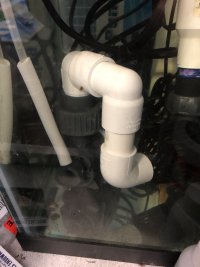
The trickle box is exhausted though as it has most of the decaying matter trapped in it:

1625821031135.jpeg


Pipe on the left pours the water onto the sponges silently with pretty much no breaking of the water. Pipe on the right is the emergency overflow and acts as an exhaust to vent out the gases from the decay. Rest of the box is sealed as well as possible with just the lid fastened down. When buying boxes to try I tested this by filling the box up with water, putting the lid on and turning it upside down. It didn’t leak so good enough and just so happened to be tapered sides that slot perfectly into the width of a Dennerle 55l but 1-2mm over to ensure a good fit.

Another component is having an overflow that doesn’t break the water when tuned in:

1625824818358.jpeg


This here is where the losses are usually. By gently pouring the water over you end up with water surface exposed to the air, but no breaks. This section isn’t sealed, it has a loose lid.

Finally, there’s your surface agitation:

1625824925010.jpeg


If everything is working harmoniously you will notice no less efficiency getting Co2 dissolved into the water than you would with a canister. Plus, a theoretical o2 advantage for your filtration.

So really @Wookii the only chamber that is really sealed is the K1 media section. However, it hasn’t needed air being pumped into there as there isn’t much material breaking down in that area, decay is kept in the sponges in the trickle box that does have a vent/standpipe. But more emphasis has been placed on ensuring there’s no breaking of the water outside that section.
 
So really @Wookii the only chamber that is really sealed is the K1 media section. However, it hasn’t needed air being pumped into there as there isn’t much material breaking down in that area, decay is kept in the sponges in the trickle box that does have a vent/standpipe. But more emphasis has been placed on ensuring there’s no breaking of the water outside that section.

Thanks @Geoffrey Rea (and sorry to @Mr.Shenanagins if this is going too far OT - feel free to move these posts to your "Taking a Sump. . ." thread Geoff).

My question really related to that K1 chamber, since that is the 'trickle' section that aims to dissolve additional O2 into the water - the main benefit of running a trickle (wet/dry) filter in a planted tank. Does not exchanging the air in this compartment reduce the O2 that dissolves into the water - or is this a non-issue because a) its not actually air tight, and b) O2 saturation from photosynthesis during the photo period replenishes it for lights out anyway.

Also that plastic container was a very lucky find. I've not been able to find one anywhere (and I have searched very extensively) that fits so well on standard tank dimensions. Do you remember where you got it?
 
Does not exchanging the air in this compartment reduce the O2 that dissolves into the water - or is this a non-issue because a) its not actually air tight, and b) O2 saturation from photosynthesis during the photo period replenishes it for lights out anyway.

This is the point. I have to say theoretical o2 advantage as the only way to test it is to run an empty setup and measure dissolved o2 - which I didn’t and should have. With the plants it’s always high dissolved o2 but the system doesn’t gas off willingly.

Also that plastic container was a very lucky find. I've not been able to find one anywhere (and I have searched very extensively) that fits so well on standard tank dimensions. Do you remember where you got it?

Extremely fortuitous! But hopefully widely available:

1625827922998.jpeg


1625828145876.jpeg


From B&Q @Wookii and fits in the Dennerle 55l like a glove.
 
@Mr.Shenanagins I have used needle wheel pumps in many applications including planted tanks.
They work very well as a low maintenance and consistent source of C02.
However there are needle wheel pumps and there are ‘needle wheel pumps‘ or in other words some work miles better that others!
Many years ago there was a strong development in needle wheel powered protein skimmers, the best pumps cause massive cavitation and really break down the bubbles to an ultra fine mist but in turn do not produce much flow and very little head of pressure.
I notice your pump is producing quite a coarse mist I also notice you might be causing a lot of restriction into the pump inlet?
I cant really tell from your pictures if that is the only pump inlet but, if so I think you would benefit from a better way to get the gas into the pump?
 
Last edited:
@Mr.Shenanagins I have used needle wheel pumps in many applications including planted tanks.
They work very well as a low maintenance and consistent source of C02.
However there are needle wheel pumps and there are ‘needle wheel pumps‘ or in other words some work miles better that others!
Many years ago there was a strong development in needle wheel powered protein skimmers, the best pumps cause massive cavitation and really break down the bubbles to an ultra fine mist but in turn do not produce much flow and very little head of pressure.
I notice your pump is producing quite a coarse mist I also notice you might be causing a lot of restriction into the pump inlet?
I cant really tell from your pictures if that is the only pump inlet but, if so I think you would benefit from a better way to get the gas into the pump?
Thanks for the reply! What would be your suggestion? And your saying that a smaller inlet is making the needle wheel work inefficiently?
 
Do the CO2 bubbles reach the substrate level ? from the 'vid' it is hard too tell, trouble with 'duck bill' outputs is they are not the best for high tech planted tanks and do low tech planted tanks and fish only tanks better. However not having a carpet you seem to be getting away with it as plants look good.

Being able to see the CO2 bubbles is a very useful at assessing the flow in the tank, once flow is good the bubbles are a PITA IMO
Yeah it actually works out just fine, the only plant I’m struggling with right now is AR mini. And it’s right next to some Hygro kompact that is flourishing so go figure.

@Geoffrey Rea and @Wookii no issues here, I appreciate all the input and questions.
 
@foxfish I haven’t intentionally blocked it, I just shoved the diffuser into the pvc inlet. I may try just sticking the CO2 into the Venturi as it’s intended for air suction and see how that works as well.
 
Update @Geoffrey Rea @foxfish @Wookii

Today I decided to try injecting the CO2 the same way the needle wheel is intended to draw air in through the Venturi. This is working excellent and actually even more efficient than my original plan of placing the diffuser in front of the inlet. The bubbles appear even smaller now. It’s also much quieter in operation now and I cannot even hear it within a few feet of the tank. I’ll make another video when I get a chance, this way @Zeus. can see the bubbles reach the substrate. 🤪
 

Attachments

  • 3C6106A5-E0A3-418D-894F-979EF84A529F.jpeg
    3C6106A5-E0A3-418D-894F-979EF84A529F.jpeg
    1.3 MB · Views: 120
Back
Top