Outflow, right after the filter. So basically you recirculate the Co2 so that is dissolves in the water prior entering the reactor again. You could add it to a pump too if you like.Looks nice! Did you also add a venturi loop in the end or did you skip it? If so did you put the venturi loop back in the outflow or inflow hoses? Or a dedicated pump?
-
You are viewing the forum as a Guest, please login (you can use your Facebook, Twitter, Google or Microsoft account to login) or register using this link: Log in or Sign Up
You are using an out of date browser. It may not display this or other websites correctly.
You should upgrade or use an alternative browser.
You should upgrade or use an alternative browser.
DIY Barr's venturi design reactor build
- Thread starter Nigel95
- Start date

There are obviously lots of methods but not much actual choice to purchase.
The venturi device can be used and is interesting to watch but they can be noisy and not always necessary.
In fact a build up of gas will pressurise the vessel and offer a surface to surface contact between the C02 and the water. That is a method in its own right and running a ‘pressurised reactor‘ was a popular method when C02 was a popular additive in marine tanks.
The main consideration when you get a big up of gas is the fact it continues to disolve well after the C02 supply is turned off.
In my mind there are a few aspects that i consider very helpful when designing a reactor.
One, is being able to see what is going on inside ie .... a clear vessel.
Two, is having enough valves and a bypass so you have total control over the flow.
I have found that fine tuning C02 reactors can make all the difference between hardly working at all to being very efficient!
From my own personal experience i would say the larger the reactor the better!
What we are trying to do is make a small reactor that works as well as a large reactor.
It is all good fun......
I built a particular design about 10 years ago that used a cut down plastic bottle inside a water treatment vessal .
I still have it and it still works as it did 10 years ago, 4000+ lph with quite a high bubble count, all bubbles totally dissolved and none escaping the reactor.
However other folk built similar reactors based on my design but useing slightly differnt shaped vessael and plastic bottles and they did not find my own succses !
That proves to me how fickle reactor design can be.
Zeus.
Fertz Meister
Do you have any idea how much space approximately it takes to fit one of those setups you mentioned?
well the trouble with hoses is you cant bend then fast or they kink so it can soon get hoses all over the place. Thats the nice thing about using a complete PVCU fittings and less jubilee clips as well.
Would love to add that venturi loop as well as it seems a nice way to get the o2 + co2 build up back in the system.
Yes, I would too (plan to in near future)
Outflow, right after the filter. So basically you recirculate the Co2 so that is dissolves in the water prior entering the reactor again. You could add it to a pump too if you like.
or just after the branch of the 'T' branch for the bypass in may case
Yes probably read most of the posts at the time, but the Cost of two APS EF2 was good at the time and they fitted, not doing a ventri system was a mistake IMOThese are dimensions that have been tested and proven to work. There is no need to oversize things when it's not needed. Now you can certainly vary dimensions but these are what works for most folks. At least that's what I have read over and over again. Obviously the bigger the tank and the bigger the reactor needs to be since you'll have bigger pumps with stronger flow. The whole idea is to slow the flow and break bubbles small enough so that mixing with water is optimal. How you do it doesn't really matter. These 2 designs Rex Griggs and Cerges do exactly the same, just with different hardware.
Yeap that's good. The further back you put the Co2 the better. Here Tom's Barr way:
Dual venturi DIY External CO2 reactor
And here is the method I used:
Aquatic Plant Central - View Single Post - DIY Inline reactor plans
(the post is not from me but I did the same)
In fact a build up of gas will pressurise the vessel and offer a surface to surface contact between the C02 and the water. That is a method in its own right and running a ‘pressurised reactor‘ was a popular method when C02 was a popular additive in marine tanks.
The main consideration when you get a big up of gas is the fact it continues to disolve well after the C02 supply is turned off.
Yes I believe it helps too, big pocket of air and wider reactor, I think thats why I am able to drop the pH so fast.
Yes, wrote to APS at time and no joy, but you can get them now I believe.One, is being able to see what is going on inside ie .... a clear vessel.
I have fairly recently reduce the pH drop to about 1.0pH and it takes longer to get a stable pH as all I did was reduce the working PSI from 50psi to 30psi
Asked the guy and no problem if I want two additional holes but it's not possible in the top of the reactor due too the vent valve over there. I wonder if this kills the idea of the venturi loop? If I am correctly I could still have an extra hole on the opposite of the reactor of where the co2 enters and loop this to the outflow hoses of my filter? And then I still have a manual valve on the top? Please correct me if I'm wrong!
Then I would go for this reactor with no bypass for the 60p I think.
And this reactor but with 10cm extra height and with bypass for my 360l tank.
Or maybe the APS EF2 clear vessel route.. cheaper but more work also.
Checked with someone else who has this design and on his smaller tank 60l the basic reactor works fine. On his 120cm tank he couldn't get the ph drop without the bypass.
Last edited:
Zeus.
Fertz Meister
The vent valve can be converted to an outlet for the venturi feed - it would make a perfect vent IMObut it's not possible in the top of the reactor due too the vent valve over there.
Plus a cant see a good reason why the CO2 inlet cant just 'T' into the ventri loop tubing- why does it need a separate inlet???
That's exactly what the vent port is fornot possible in the top of the reactor due too the vent valve over there
")
I would be you I would build it. It would cost less and you will do it to your own specs. Fun project too.
Wait so why does the top have to be converted? The top is already a manual valve if I wanted to manually remove the gas? I probably still don't understand the concept fully lol.The vent valve can be converted to an outlet for the venturi feed - it would make a perfect vent IMO
Plus a cant see a good reason why the CO2 inlet cant just 'T' into the ventri loop tubing- why does it need a separate inlet???
If I make a T or Y airline connection for 1) the co2 inlet and 2) venturi airline towards the filter. Does it work properly then? This isn't my field but how does the build up co2+o2 escape from the the venturi airline, when it's next to where the co2 gets pumped in with pressure? Doesn't that work against each other?
Zeus.
Fertz Meister
Well 'if' the venturi creates enough suction/pressure drop all the gas/air will be circulated by it so it should work. Mine have no vent ports (unless I loosen the fittings)if they get air in during maintenance a few hours later when the the system is running its all gone. The top 'vent' on the reactor chamber just speeds the process upWait so why does the top have to be converted? The top is already a manual valve if I wanted to manually remove the gas? I probably still don't understand the concept fully lol.
If I make a T or Y airline connection for 1) the co2 inlet and 2) venturi airline towards the filter. Does it work properly then? This isn't my field but how does the build up co2+o2 escape from the the venturi airline, when it's next to where the co2 gets pumped in with pressure? Doesn't that work against each other?
So why have an extra hole in the pipework/hardware, just 'T' into venturi pipe, this only just dawned on me today
Zeus.
Fertz Meister
@Nigel95 I think you have inspired me to find a potential DIY solution for myself, not the cheapest

110 mm clear PVC pipe
Then just use off the shelf 110mm soil pipe fittings and solvent weld it all up, drill a few holes for pipe fitting etc and weld them up too.
and would have enough 110 PVC left to go into production
110 mm clear PVC pipe
Then just use off the shelf 110mm soil pipe fittings and solvent weld it all up, drill a few holes for pipe fitting etc and weld them up too.
and would have enough 110 PVC left to go into production
PVC is really easy to work with but apart from being expensive it is actually more opaque rather than clear.
Also it is very soft compared to acrylic so scratches just like that!
However it is a great product to experiment with and it will do the job.
A few years back one member designed and made quite popular, a very tall reactor from 50mm PVC .
It was around one meter long and very basic but also very effective.
Trying to remember his name ... he had a huge square tank with chocolate gouramis ?
Alex perhaps ?
Last edited:
Good luck buddy looking forward to see your result and your experience!@Nigel95 I think you have inspired me to find a potential DIY solution for myself, not the cheapest
View attachment 157560
110 mm clear PVC pipe
Then just use off the shelf 110mm soil pipe fittings and solvent weld it all up, drill a few holes for pipe fitting etc and weld them up too.
and would have enough 110 PVC left to go into production
Trying to remember his name ... he had a huge square tank with chocolate gouramis ?
Alex perhaps ?
Alastair?
Do you mean this thread @foxfish :
DIY Project - Co2 reactor build for Fluval FX5
Following an earlier thread regarding my interest in building a DIY reactor for a FX5 filter, I've now taken the plunge and ordered all parts necessary with some help from Mr Ed Seeley (thanks mate). The parts have arrived And this is what I've received. 1. 1 meter of 2 inch PVC pipe (metric)...
www.ukaps.org
Mr.Shenanagins
Member
Never tried using the external one, but the internal Venturi design works fantastic.
What exactly is an internal Venturi design?internal Venturi design
Zeus.
Fertz Meister
When when 'I' use the term 'internal Venturi' I am refering to the Venturis location relative to the CO2 reactors chamber, if its in the chamber or within the chamber container then its 'internal IMO, external venturi is outside of reactor chamber. External should be more efficient as you pointed out the bubbles have longer contact with water.What exactly is an internal Venturi design?
Wookii
Member
When when 'I' use the term 'internal Venturi' I am refering to the Venturis location relative to the CO2 reactors chamber, if its in the chamber or within the chamber container then its 'internal IMO, external venturi is outside of reactor chamber. External should be more efficient as you pointed out the bubbles have longer contact with water.
How would you include a venturi inside the chamber?
Was going to ask the same 😅How would you include a venturi inside the chamber?
Zeus.
Fertz Meister
How would you include a venturi inside the chamber?
CO2 APS EF2 reactor with internal Venturi fitted
it works but not was well as I hopedMr.Shenanagins
Member
What exactly is an internal Venturi design?
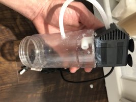
DIY internal Reactor, great for Yeast CO2 users!
Here's a small little highly effective DIY Reactor that cost about 11$ with the powerhead, or about 2-3$ without. Materials: 12" rigid airline tubing 3/16" OD 4" L x 2" OD Viewtainer Lighter Snips or shape knife Metal rod/small screwdriver, about 1/8" or 3/16" diameter Procedure...
Internal meaning the reactor is either inside the aquarium or inside the sump. I’ve attached the one I made, works well in my sump. It’s placed right over my pump so that when bubbles escape through the bottom they are immediately sucked into the pump and into my tank
Attachments