Zeus also built a PLC controlled fish tank. Below is Zeus's build notes & pictures.
https://www.ukaps.org/forum/threads...ntrol-your-fish-tank.42993/page-3#post-489803
How to use a PLC to control your fish tank
This article explains how you can use a PLC (programmable logic controller) to control all your fish tank electrics, namely lights, CO2, dosing pumps, air pumps etc, so instead of having multiple mains timers, you now control everything from a single PLC unit.
With more advanced design ideas (not shown here), one can implement automatic water changers and CO2 & temperature controllers.
What is a PLC.
According to the great Internet of truths, Wikipedia, a PLC is;
“a digital computer used for automation of typically industrial electromechanical processes, such as control of machinery on factory assembly lines, amusement rides, light fixtures or high tech fish tanks” (my bit in italics).
Below are some diagrams of what is possible, fish tank control wise, using a PLC.

Figure 1 PLC Example 1
Automated electrics. Make use of PLC timer facilities to turn lights, CO2, dosing pumps on at correct times of the day.

Figure 2 PLC Example 2
Automatic reverse osmosis (RO) water changer. On Thursday night (for instance), the PLC turns the RO on and fills water butt to half full, as sensed by level switch. It then fills rest of water butt with mains water giving 50:50 RO & tap water. Then it adds dechlorinator and turns on the water heater to warm the water. It then pumps out 50% of tank water, the 50% level being sensed via float level switch in the tank. Finally it pumps the contents of water butt into tank the tank full level being sensed by a float switch in the tank. Once every so often the PLC reverse flushes the RO unit, to keep the membrane clean.

Figure 3 PLC Example 3
Water temperature and CO2 ppm controller. The PLC measures the water temperature and turns heater on and off at desired temperature. It also measures the pH (and temperature compensates the pH probe) and turns on enough CO2 to give a pH drop of 1 unit, giving 30ppm CO2.
This article is mainly concerned with diagram 1, I will leave it to others to implement the other two diagrams.
Unfortunately using a PLC is not really a standard off the shelf solution, DIY construction, wiring, setup and programming is required.
The ability to wire up mains electrics safely is required, if you can strip wires and wire a 13A plug correctly you are probably OK.
As well as wiring in its simplest form a PLC will require some setup/configuration, not really programming per se, but will require configuring of timers and outputs.
I thought the programming bit would be complicated but upon investigation the actual programming was very easy and quite simple.
The PLC used in the article.
Below is the PLC (and expansion module) I am using and will be describing are Siemens Logo!8 series.
The module with display on the left of the picture, is the main PLC with 8 inputs and 4 relay switched outputs. It is connected to an expansion module, the module on the right, with a further 8 inputs and 8 relay outputs. This is a 230V (and 120V) device and can be used directly off the mains supply. This setup gives 12 relay switched outputs and mains level 16 inputs.
Note this is Logo!8 series, the older models Logo!7 and earlier PLC’s are not equivalent.
This PLC also has an Ethernet interface that can be used to program upload & configure, as well as remotely monitoring its operation, so no manufacturer specific (ie expensive) programming lead are required.

Figure 4 Siemens Logo! PLC and Expansion Module
Why should I use a PLC as opposed to time switches ?
Main reason, in one word, is reliability.
PLC’s are industrial control electronics and are built from components that are in a completely different league of reliability compared to the components used in most mains time switches, that all now seem to originate from China. Siemens for instance quote a lifetime of over 100,000 hours for their devices and relay switching operations rated at over 3 million operations.
I have been through so many mains time switches on my fish tank, all failing in one way or another after a couple of years use.
Over the years I have had time switches that;
- Completely die. No display, no response.
- Very commonly, just reset to 00:00 and loose all their time clock settings.
- Their internal batteries run flat, so after a power failure they don’t retain their settings.
- Sometimes fail to turn on for their time period.
- More dangerously for fish keeper, fail to turn off at end of time period or jam on. OK for air pump, no damage done, but I had a time switch fail to turn off and dumped a large amount of liquid carbon into my tank, killing both plants and fish.
I have also experimented with wireless controlled mains sockets, nice as you can get many sockets in a small space, but I have had a few socket failures, where they no longer respond to the wireless commands. Also I have also confirmed that the words “wireless” and “reliable” do not occur in the same sentence, I have had sockets working for years then randomly one day, fail to turn on (or off). I ended up dumping 1litre of macro EI solution into my tank, when my dosing time switch failed to turn off after 15minutes. Luckily as fish are not affected by high nitrate and phosphate all was well.
My most reliable time switch, I bought early 1990’s, was in fact a UK made one, by Timeguard and still works. It is just rather large. Timeguard still make & sell timers, which are highly regarded but cost £25 each.
Also bear in mind, cost. A PLC will cost around £100, further I/O module another £100 and development software, if required, £40 odd. But compare this to buying the much more inconvenient time switches at say £10-£20 a go.
PLC’s
I first started looking to use a PLC in around 2012. I had converted my tank to high tech and pretty soon was messing around with 6 or more time switches, lights, CO2, power head, air pump, macro dosing, micro dosing and liquid carbon dosing. I kept having the feeling there must be a simpler, more reliable way of controlling the electrics. Also I started suffering failed timers as well, luckily failed to work so no damage done.
However back then there were major issues with PLC’s, as far as I was concerned, that put the PLC controller project on a back burner:
- Cost. A decent PLC was £300 or more.
- Most PLC’s were 12V or 24V powered, not mains, thus a 12/24V power supply would also be needed.
- Development software for the “better” PLC’s was £150 or more.
- Most PLC’s needed to be programmed via RS232 leads !!!.
- A USB to RS232 lead, required to use a modern PC, would be needed, another £100 odd.
- Using a USB to RS232 lead meant the development PC would have to be located locally to the fish tank to allow setting up and program updating.
- No networking capability.
- No way to monitor/control over the Internet (might be a good thing of course).
However Siemens introduced their Logo!8 PLC's with the following interesting features:
- Start at £100 (8 in 4 out).
- Mains powered versions available, no messing with power supplies.
- Development software only £40.
- Ethernet connection for web access, programming and setup. No expensive programming lead or PC located near PLC required.
- Using the Ethernet it can be monitored/controlled over the Internet.
DIY PLC's
Of course there is nothing to stop you making your own PLC from a processor module eg Raspberry PI, Beagle Board etc, or a PC and a collection of relays, switches and some software. Many companies offer DIY PLC modules or more suitably PLC motherboards with relays and mains inputs that you plug your Raspberry Pi (or other processor board) into.
I spent ages looking into this as a solution and as an electronic engineer and programmer by trade, I initially thought this would the best way forward.
However all of these suffered, in my opinion, from major drawbacks.
- Would require some serious DIY construction to make suitable cases, power supplies and wiring for these modules.
- Most solutions would end up being physically large and there is only so much room under my fish tank.
- Would require some serious programming to get these setups working. I am a programmer, by trade, thus was well aware of the complexity required.
- There is open source PLC programming software, you draw block diagrams of the functions you want, but is all very amateur compared to the commercial £250 proper development software.
- Interfacing to displays and buttons is not easy and would require much programming effort.
- Reliability. People who have built their own PLC’s still report reliability issues both flaky hardware and buggy software.
- Cost. By the time you have added all the bits and pieces up, Rasberry PI £20, PLC motherboard £80, power supply £10...it ended up not being any cheaper than commercial PLC.
So in the end I decided I wanted to spend time setting up and configuring my PLC rather than spending time programming and building a PLC.
Siemens Logo! 8 PLC’s
An overview of the Siemens Logo! 8 series is below.
http://w3.siemens.com/mcms/programmable-logic-controller/en/logic-module-logo/overview/Pages/default.aspx
I bought a Logo! 8 starter kit for £150 from Conrad electronics. It shipped from Germany in a couple of days.
The LOGO! 8 Starter Kit 230RCE starter kit is part number 6ED1 057-3BA02-0AA8.
http://w3.siemens.com/mcms/programmable-logic-controller/en/logic-module-logo/logo-starter-kit/Pages/Default.aspx#LOGO__208_20Starter_20Kit_20230RCE
This includes a Logo! 8 module, part number 6ED1052-1FB00-0BA8, Logo! Soft Comfort V8 (development software), WinCC Basic V13, nice green industrial Ethernet lead and a Siemens screwdriver all in a tough storage box.
I also bought a LOGO! DM16 230 R module providing another 8 inputs and 8 outputs. Part number 6ED1055-1FB10-0BA2
Below is the link to the Logo!8 hardware user manual
https://support.industry.siemens.com/cs/document/109741041/logo!?dti=0&pnid=13618&lc=en-GB
If you are "going advanced" you will need the full version of Siemens PLC development software Logo!8 Soft Comfort.
http://w3.siemens.com/mcms/programmable-logic-controller/en/logic-module-logo/demo-software/pages/default.aspx
There is a demo version available so you can play & test & simulate. However the demo version cannot upload programs to the PLC.
Below is the link to the Logo!8 Soft Comfort user manual.
https://support.industry.siemens.com/cs/document/100782807/logo!soft-comfort-online-help?dti=0&pnid=13617&lc=en-GB
You will also need some form of box/enclosure to put the PLC in, to cover up the mains terminals and wiring.
I used a Bopla box from RS (rswww.com), part number 773-9632, for £30 odd.
If you search Amazon for “Siemens logo case” you will find a seller selling nice acrylic cases for Logo devices. Check sizes before buying.
Wiring up your PLC, simple 4 channel version.

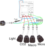
Figure 5 PLC Wiring
Basically you need to wire the PLC as in the diagram above. The PLC output relays connect to 13A trailing sockets to allow items to be easily plugged in eg light, CO2 etc. Using a 13A socket enables you to easily disconnect the item if needed for repair, replacement or upgrade.
Mains live needs to go to the PLC pin L1 (at the top) and connection pin 1 of all 4 relays.
Connection pin 2 of the relays needs to go to the item you wish to control. eg in picture above, relay 1 is tank lighting, relay 2 is CO2 solenoid, relay 3 is macro dosing pump & relay 4 is micro dosing pump.
All this wiring needs to be done neatly, preferably in an enclosure/box, so that accidental water splashes won't be a shock risk (or damage the PLC).
Further ideas for mounting & connecting are shown below.

Figure 6 PLC Build Ideas
Setting up the PLC
Once your PLC is wired up, mains supply to its power inputs and connected to your tanks electrical devices (lights, CO2, pumps etc) the PLC will need setting up and programming.
First time setting up is quite simple, basically at this stage it consists of entering the correct date and time and time zone. See page 282 of user manual on how to set the clock and date using the LCD and cursor keys on the front panel.
Programming the PLC
As for programming, this can be done in 3 ways:-
Front panel programming.
Suitable for simple setups ie lights on at 5pm off at 11pm, but is rather like decorating your house via the letterbox, possible to do if simple, but hard for anything complicated.
This is a very easy way to start, requiring no development software.
Development software running on a PC
With the development software Logo! Soft Comfort you connect “blocks” in the software ie a timer block connected to an output block meaning the output relay is now controlled via a timer, perfect for fish tank lights, CO2 etc.
Below is an example for a light timer with lights connected to output relay Q1. This timer is lights on 17:00-23:00 on Sunday to Thursday and 18:00-23:45 on Friday and Saturday. The timer block has three time slots, if you require multiple time periods.

You then simply upload the program to the PLC, via the network interface and start the program running, job done.
This is a much better method than entering your program via the front panel, as you can also simulate & test your design, in Logo!Soft Comfort, before uploading to the PLC. It is also possible monitor/debug what is going on in the PLC to test & verify your design again using Logo!Soft Comfort.
µSD memory card
You can also load a .BIN file (generated by a licensed copy of Logo!Soft Comfort) onto an µSD card, insert into the PLC and power it on and the program will run. Job done.
No development software, no front panel programming is needed
The program can be edited/modified via the front panel keys, but is generally hard and difficult to do.
Programming via front panel example
Below is an example of programming, via the PLC front panel with the following specification.

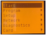
With PLC powered on using the cursor, OK and ESC front panel keys follow the pictures below.


Select “Program” Select “Program “, press OK Select “Edit Prog”, press OK
The final picture shows that block B1 (our weekly timer block) is connected to output Q1. Whenever the timer block output is set, based on time (and off times) the Q1 relay, connected to our lights, is closed.

To change the on & off times, whilst the PLC is running.

If this program is downloaded into Logo!Soft Comfort, it looks like this.

Figure 7 PLC Program
If you can’t be bothered to enter the program then download the .BIN file below to a µSD card (formatted FAT32), pop into PLC, power on, done. Also included is the .lsc source.
https://1drv.ms/f/s!AgIGUdnorxMQl9wov206rryCrnkaJg
My Controller , The “Big Boy” PLC
The PLC controller I built is shown below.

Figure 8 PLC Controller Under my tank.
My basic design idea started with the following:
- Had to fit in my existing Juwel cabinet.
- As tank is in my lounge and PLC will be visible, it had to have WAF (wife acceptance factor).
- Had to have manual overrides, so that I could turn lights, filters etc on & off for when doing water changes, adding fish etc. For this I decided to use toggle switches connected to the PLC’s inputs rather than settable via the PLC front panel buttons.
- A quick toggle on the switch turns toggles the relevant output on or off. Handy to quickly turn the lights on and off when feeding and quick tank inspections.
- A longer held toggle, 3 seconds, disables/enables the relevant timer output.
- Use the display to indicate status, when outputs are on.
- Time settings and enable/disable configurable via front panel buttons, so the access to a PC is not required to change settings.
- Accessible via network for monitoring and configuration.
I used the 240V Logo!8 module along with the 230V 8 input and 8 output module, giving 16 inputs and 12 outputs in total.
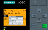
My design has the following timer specifications. The holiday mode has reduced lighting & dosing times for when on holiday. Holiday mode is set via front panel keypad or web access.

*Sets either just 2 tubes on or all 4 tubes on.
+ For future use.
** Using a 3ml per minute pump giving about 40ml in my 180l tank.
++ Using a 1ml per minute pump giving about 5ml in my 180l tank.
Hardware Build.
I used a Bopla case from RS, part number 7739632 (about £30). http://rswww.com. This has a hinged transparent front door.
It was mounted in the centre section of my Juwel Vision 180 stand, held in by screws at the top and an aluminium bracket underneath. All the mains connections come out the back of the case and pass through into the cupboard next door, via an 80mm hole. This is where all the equipment is plugged in.
Inside the case the PLC and expansion module was mounted on an aluminium bracket. See Figure 9.
The long bolts in Figure 9 allowed correct setting up of PLD height, within the box, so the side fixing holes could be drilled accurately. These bolts were replaced with shorter bolts once side fixing was complete.

Figure 9 PLC Mounting Bracket.
A suitable hole was cut through the front panel to allow the PLC keys to be accessed. I covered it with a plastic film (decorator’s carpet protector) to stop scratches during the build. I even flame polished the cut edges, though one ended up flame “charred”.

Figure 10 Front Panel Cutout.
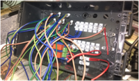
The internals was wired up as in Figure 11. The “arrowed wires” in the diagram go to further mains sockets to connect to devices. The wires go out to single 13A mains cable sockets so the devices, lights, solenoid etc can be simply plugged in.

Figure 11 PLC Wiring.
The relay outputs of the PLC were wired for the following functions.

The corresponding PLC inputs I1 to I12 were wired to 6 off front panel toggle switches. The labelling (including missing FOOD ??) was made using a laminator.

Figure 12 Front Panel Switches.
I used centre lockable toggle switches, you have to pull the toggle out before it will toggle up or down. This is to prevent accidental knocking of the switches. These were from www.mouser.co.uk part number 633-M201805 @ £4 each.
The filter and heater connections were slightly different and were connected via a relay board, fitted in the case.

Figure 13 Filter and Heater Relay Board.
The function of the relay board was to “invert” the operation of the PLC outputs Q10 (filter) & Q11 (heater) so that if all PLC outputs are off, the filter and heater would be on. Energising PLC Q10 or Q11 switches off the filter or heater. This is so that, with all PLC outputs off, as in most of the time when not PLC doing anything “interesting” or when programming or fiddling, the filter and heater would always be on.
Also if the PLC crashed !!!! (very very very very never heard of unlikely) the filter and heater would always be on.
Figure 14 shows wiring inside in progress.
This also shows, on right hand side, two 6.3A fuses (not wired yet in picture).
One fuse was used solely for the filter and heater and other fuse on all the other devices. This was to ensure a fault in some non essential item eg light, CO2 etc did not knock out filter and heater.
On the bottom right is an Ethernet bulkhead connector to connect to the PLC Ethernet. Ethernet connection within the case was made using a 25cm flat Ethernet cable.
All wire ends were crimped with bootlace ferules to enable easier insertion into the relevant screw terminals as well as securing multiple wires in one ferrule.
Lacing cord was used to keep the wire bundles under control and in place. Cable number markers were used to so that wires could be easily tracked.

Figure 14 Wiring in progress.
The extra holes in the case above were for pH probe & temperature probe...however complete lack of space, both wiring and software wise, prevented that use. A future upgrade ?

Figure 15 Testing before wiring the switches.

Figure 16 It was a squeeze when all done.

Figure 17 Done, ready to put in cabinet.

Figure 18 All Cables Squeezed in cabinet next to controller.
Fish Feeder
Another item to control is a fish feeder. As most fish feeders are standalone battery operated and generally include some form of timer control ie feed twice every 24 hours some internal rewiring would be required.
Opening up a Hydor fish feeder revealed batteries, controller circuit board, motor, a toothed wheel and a sensing switch.
Its normal operation is as follows:
- At feeding time the controller energises the motor
- The toothed wheel to rotates and vibrates.
- This wheel is connected to the food container, which rotates one revolution whilst vibrating out a portion of food.
- The toothed wheel has a tooth on it which pushes a micro switch so the controller can tell the wheel has done one revolution.
So by cutting internal wires and PCB tracks on the controller board circuit board the following circuit was obtained. The controller board had to be left in as part of it formed connections to the battery. The switch should be open circuit when pushed by the tooth on the wheel.

Figure 19 Fish Feeder Wiring.
The operation is now as follows:
- The PLC controller, connected to the fish feeder by a 3.5mm to 3.5mm connecting lead, closes its relay for 1 second.
- This powers the motor which rotates the toothed wheel.
- Once rotated the switch closes keeping power applied to the motor.
- The PLC opens its relay after 1 second.
- The toothed wheel keeps rotating until the switch opens, due to the tooth on the wheel, cutting power to the motor.
- Fish are fed.

Figure 20 Fish Feeder, Motor, Toothed Wheel and Switch.
Continued in part 2....
https://www.ukaps.org/forum/threads...ntrol-your-fish-tank.42993/page-3#post-489803
How to use a PLC to control your fish tank
This article explains how you can use a PLC (programmable logic controller) to control all your fish tank electrics, namely lights, CO2, dosing pumps, air pumps etc, so instead of having multiple mains timers, you now control everything from a single PLC unit.
With more advanced design ideas (not shown here), one can implement automatic water changers and CO2 & temperature controllers.
What is a PLC.
According to the great Internet of truths, Wikipedia, a PLC is;
“a digital computer used for automation of typically industrial electromechanical processes, such as control of machinery on factory assembly lines, amusement rides, light fixtures or high tech fish tanks” (my bit in italics).
Below are some diagrams of what is possible, fish tank control wise, using a PLC.
Figure 1 PLC Example 1
Automated electrics. Make use of PLC timer facilities to turn lights, CO2, dosing pumps on at correct times of the day.
Figure 2 PLC Example 2
Automatic reverse osmosis (RO) water changer. On Thursday night (for instance), the PLC turns the RO on and fills water butt to half full, as sensed by level switch. It then fills rest of water butt with mains water giving 50:50 RO & tap water. Then it adds dechlorinator and turns on the water heater to warm the water. It then pumps out 50% of tank water, the 50% level being sensed via float level switch in the tank. Finally it pumps the contents of water butt into tank the tank full level being sensed by a float switch in the tank. Once every so often the PLC reverse flushes the RO unit, to keep the membrane clean.
Figure 3 PLC Example 3
Water temperature and CO2 ppm controller. The PLC measures the water temperature and turns heater on and off at desired temperature. It also measures the pH (and temperature compensates the pH probe) and turns on enough CO2 to give a pH drop of 1 unit, giving 30ppm CO2.
This article is mainly concerned with diagram 1, I will leave it to others to implement the other two diagrams.
Unfortunately using a PLC is not really a standard off the shelf solution, DIY construction, wiring, setup and programming is required.
The ability to wire up mains electrics safely is required, if you can strip wires and wire a 13A plug correctly you are probably OK.
As well as wiring in its simplest form a PLC will require some setup/configuration, not really programming per se, but will require configuring of timers and outputs.
I thought the programming bit would be complicated but upon investigation the actual programming was very easy and quite simple.
The PLC used in the article.
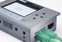
Below is the PLC (and expansion module) I am using and will be describing are Siemens Logo!8 series.
The module with display on the left of the picture, is the main PLC with 8 inputs and 4 relay switched outputs. It is connected to an expansion module, the module on the right, with a further 8 inputs and 8 relay outputs. This is a 230V (and 120V) device and can be used directly off the mains supply. This setup gives 12 relay switched outputs and mains level 16 inputs.
Note this is Logo!8 series, the older models Logo!7 and earlier PLC’s are not equivalent.
This PLC also has an Ethernet interface that can be used to program upload & configure, as well as remotely monitoring its operation, so no manufacturer specific (ie expensive) programming lead are required.
Figure 4 Siemens Logo! PLC and Expansion Module
Why should I use a PLC as opposed to time switches ?
Main reason, in one word, is reliability.
PLC’s are industrial control electronics and are built from components that are in a completely different league of reliability compared to the components used in most mains time switches, that all now seem to originate from China. Siemens for instance quote a lifetime of over 100,000 hours for their devices and relay switching operations rated at over 3 million operations.
I have been through so many mains time switches on my fish tank, all failing in one way or another after a couple of years use.
Over the years I have had time switches that;
- Completely die. No display, no response.
- Very commonly, just reset to 00:00 and loose all their time clock settings.
- Their internal batteries run flat, so after a power failure they don’t retain their settings.
- Sometimes fail to turn on for their time period.
- More dangerously for fish keeper, fail to turn off at end of time period or jam on. OK for air pump, no damage done, but I had a time switch fail to turn off and dumped a large amount of liquid carbon into my tank, killing both plants and fish.
I have also experimented with wireless controlled mains sockets, nice as you can get many sockets in a small space, but I have had a few socket failures, where they no longer respond to the wireless commands. Also I have also confirmed that the words “wireless” and “reliable” do not occur in the same sentence, I have had sockets working for years then randomly one day, fail to turn on (or off). I ended up dumping 1litre of macro EI solution into my tank, when my dosing time switch failed to turn off after 15minutes. Luckily as fish are not affected by high nitrate and phosphate all was well.
My most reliable time switch, I bought early 1990’s, was in fact a UK made one, by Timeguard and still works. It is just rather large. Timeguard still make & sell timers, which are highly regarded but cost £25 each.
Also bear in mind, cost. A PLC will cost around £100, further I/O module another £100 and development software, if required, £40 odd. But compare this to buying the much more inconvenient time switches at say £10-£20 a go.
PLC’s
I first started looking to use a PLC in around 2012. I had converted my tank to high tech and pretty soon was messing around with 6 or more time switches, lights, CO2, power head, air pump, macro dosing, micro dosing and liquid carbon dosing. I kept having the feeling there must be a simpler, more reliable way of controlling the electrics. Also I started suffering failed timers as well, luckily failed to work so no damage done.
However back then there were major issues with PLC’s, as far as I was concerned, that put the PLC controller project on a back burner:
- Cost. A decent PLC was £300 or more.
- Most PLC’s were 12V or 24V powered, not mains, thus a 12/24V power supply would also be needed.
- Development software for the “better” PLC’s was £150 or more.
- Most PLC’s needed to be programmed via RS232 leads !!!.
- A USB to RS232 lead, required to use a modern PC, would be needed, another £100 odd.
- Using a USB to RS232 lead meant the development PC would have to be located locally to the fish tank to allow setting up and program updating.
- No networking capability.
- No way to monitor/control over the Internet (might be a good thing of course).
However Siemens introduced their Logo!8 PLC's with the following interesting features:
- Start at £100 (8 in 4 out).
- Mains powered versions available, no messing with power supplies.
- Development software only £40.
- Ethernet connection for web access, programming and setup. No expensive programming lead or PC located near PLC required.
- Using the Ethernet it can be monitored/controlled over the Internet.
DIY PLC's
Of course there is nothing to stop you making your own PLC from a processor module eg Raspberry PI, Beagle Board etc, or a PC and a collection of relays, switches and some software. Many companies offer DIY PLC modules or more suitably PLC motherboards with relays and mains inputs that you plug your Raspberry Pi (or other processor board) into.
I spent ages looking into this as a solution and as an electronic engineer and programmer by trade, I initially thought this would the best way forward.
However all of these suffered, in my opinion, from major drawbacks.
- Would require some serious DIY construction to make suitable cases, power supplies and wiring for these modules.
- Most solutions would end up being physically large and there is only so much room under my fish tank.
- Would require some serious programming to get these setups working. I am a programmer, by trade, thus was well aware of the complexity required.
- There is open source PLC programming software, you draw block diagrams of the functions you want, but is all very amateur compared to the commercial £250 proper development software.
- Interfacing to displays and buttons is not easy and would require much programming effort.
- Reliability. People who have built their own PLC’s still report reliability issues both flaky hardware and buggy software.
- Cost. By the time you have added all the bits and pieces up, Rasberry PI £20, PLC motherboard £80, power supply £10...it ended up not being any cheaper than commercial PLC.
So in the end I decided I wanted to spend time setting up and configuring my PLC rather than spending time programming and building a PLC.
Siemens Logo! 8 PLC’s
An overview of the Siemens Logo! 8 series is below.
http://w3.siemens.com/mcms/programmable-logic-controller/en/logic-module-logo/overview/Pages/default.aspx
I bought a Logo! 8 starter kit for £150 from Conrad electronics. It shipped from Germany in a couple of days.
The LOGO! 8 Starter Kit 230RCE starter kit is part number 6ED1 057-3BA02-0AA8.
http://w3.siemens.com/mcms/programmable-logic-controller/en/logic-module-logo/logo-starter-kit/Pages/Default.aspx#LOGO__208_20Starter_20Kit_20230RCE
This includes a Logo! 8 module, part number 6ED1052-1FB00-0BA8, Logo! Soft Comfort V8 (development software), WinCC Basic V13, nice green industrial Ethernet lead and a Siemens screwdriver all in a tough storage box.
I also bought a LOGO! DM16 230 R module providing another 8 inputs and 8 outputs. Part number 6ED1055-1FB10-0BA2
Below is the link to the Logo!8 hardware user manual
https://support.industry.siemens.com/cs/document/109741041/logo!?dti=0&pnid=13618&lc=en-GB
If you are "going advanced" you will need the full version of Siemens PLC development software Logo!8 Soft Comfort.
http://w3.siemens.com/mcms/programmable-logic-controller/en/logic-module-logo/demo-software/pages/default.aspx
There is a demo version available so you can play & test & simulate. However the demo version cannot upload programs to the PLC.
Below is the link to the Logo!8 Soft Comfort user manual.
https://support.industry.siemens.com/cs/document/100782807/logo!soft-comfort-online-help?dti=0&pnid=13617&lc=en-GB
You will also need some form of box/enclosure to put the PLC in, to cover up the mains terminals and wiring.
I used a Bopla box from RS (rswww.com), part number 773-9632, for £30 odd.
If you search Amazon for “Siemens logo case” you will find a seller selling nice acrylic cases for Logo devices. Check sizes before buying.
Wiring up your PLC, simple 4 channel version.
Figure 5 PLC Wiring
Basically you need to wire the PLC as in the diagram above. The PLC output relays connect to 13A trailing sockets to allow items to be easily plugged in eg light, CO2 etc. Using a 13A socket enables you to easily disconnect the item if needed for repair, replacement or upgrade.
Mains live needs to go to the PLC pin L1 (at the top) and connection pin 1 of all 4 relays.
Connection pin 2 of the relays needs to go to the item you wish to control. eg in picture above, relay 1 is tank lighting, relay 2 is CO2 solenoid, relay 3 is macro dosing pump & relay 4 is micro dosing pump.
All this wiring needs to be done neatly, preferably in an enclosure/box, so that accidental water splashes won't be a shock risk (or damage the PLC).
Further ideas for mounting & connecting are shown below.
Figure 6 PLC Build Ideas
Setting up the PLC
Once your PLC is wired up, mains supply to its power inputs and connected to your tanks electrical devices (lights, CO2, pumps etc) the PLC will need setting up and programming.
First time setting up is quite simple, basically at this stage it consists of entering the correct date and time and time zone. See page 282 of user manual on how to set the clock and date using the LCD and cursor keys on the front panel.
Programming the PLC
As for programming, this can be done in 3 ways:-
Front panel programming.
Suitable for simple setups ie lights on at 5pm off at 11pm, but is rather like decorating your house via the letterbox, possible to do if simple, but hard for anything complicated.
This is a very easy way to start, requiring no development software.
Development software running on a PC
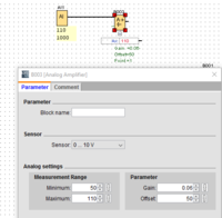
With the development software Logo! Soft Comfort you connect “blocks” in the software ie a timer block connected to an output block meaning the output relay is now controlled via a timer, perfect for fish tank lights, CO2 etc.
Below is an example for a light timer with lights connected to output relay Q1. This timer is lights on 17:00-23:00 on Sunday to Thursday and 18:00-23:45 on Friday and Saturday. The timer block has three time slots, if you require multiple time periods.
You then simply upload the program to the PLC, via the network interface and start the program running, job done.
This is a much better method than entering your program via the front panel, as you can also simulate & test your design, in Logo!Soft Comfort, before uploading to the PLC. It is also possible monitor/debug what is going on in the PLC to test & verify your design again using Logo!Soft Comfort.
µSD memory card
You can also load a .BIN file (generated by a licensed copy of Logo!Soft Comfort) onto an µSD card, insert into the PLC and power it on and the program will run. Job done.
No development software, no front panel programming is needed
The program can be edited/modified via the front panel keys, but is generally hard and difficult to do.
Programming via front panel example
Below is an example of programming, via the PLC front panel with the following specification.
With PLC powered on using the cursor, OK and ESC front panel keys follow the pictures below.
Select “Program” Select “Program “, press OK Select “Edit Prog”, press OK
The final picture shows that block B1 (our weekly timer block) is connected to output Q1. Whenever the timer block output is set, based on time (and off times) the Q1 relay, connected to our lights, is closed.
To change the on & off times, whilst the PLC is running.
If this program is downloaded into Logo!Soft Comfort, it looks like this.
Figure 7 PLC Program
If you can’t be bothered to enter the program then download the .BIN file below to a µSD card (formatted FAT32), pop into PLC, power on, done. Also included is the .lsc source.
https://1drv.ms/f/s!AgIGUdnorxMQl9wov206rryCrnkaJg
My Controller , The “Big Boy” PLC
The PLC controller I built is shown below.
Figure 8 PLC Controller Under my tank.
My basic design idea started with the following:
- Had to fit in my existing Juwel cabinet.
- As tank is in my lounge and PLC will be visible, it had to have WAF (wife acceptance factor).
- Had to have manual overrides, so that I could turn lights, filters etc on & off for when doing water changes, adding fish etc. For this I decided to use toggle switches connected to the PLC’s inputs rather than settable via the PLC front panel buttons.
- A quick toggle on the switch turns toggles the relevant output on or off. Handy to quickly turn the lights on and off when feeding and quick tank inspections.
- A longer held toggle, 3 seconds, disables/enables the relevant timer output.
- Use the display to indicate status, when outputs are on.
- Time settings and enable/disable configurable via front panel buttons, so the access to a PC is not required to change settings.
- Accessible via network for monitoring and configuration.
I used the 240V Logo!8 module along with the 230V 8 input and 8 output module, giving 16 inputs and 12 outputs in total.
My design has the following timer specifications. The holiday mode has reduced lighting & dosing times for when on holiday. Holiday mode is set via front panel keypad or web access.
*Sets either just 2 tubes on or all 4 tubes on.
+ For future use.
** Using a 3ml per minute pump giving about 40ml in my 180l tank.
++ Using a 1ml per minute pump giving about 5ml in my 180l tank.
Hardware Build.
I used a Bopla case from RS, part number 7739632 (about £30). http://rswww.com. This has a hinged transparent front door.
It was mounted in the centre section of my Juwel Vision 180 stand, held in by screws at the top and an aluminium bracket underneath. All the mains connections come out the back of the case and pass through into the cupboard next door, via an 80mm hole. This is where all the equipment is plugged in.
Inside the case the PLC and expansion module was mounted on an aluminium bracket. See Figure 9.
The long bolts in Figure 9 allowed correct setting up of PLD height, within the box, so the side fixing holes could be drilled accurately. These bolts were replaced with shorter bolts once side fixing was complete.
Figure 9 PLC Mounting Bracket.
A suitable hole was cut through the front panel to allow the PLC keys to be accessed. I covered it with a plastic film (decorator’s carpet protector) to stop scratches during the build. I even flame polished the cut edges, though one ended up flame “charred”.
Figure 10 Front Panel Cutout.
The internals was wired up as in Figure 11. The “arrowed wires” in the diagram go to further mains sockets to connect to devices. The wires go out to single 13A mains cable sockets so the devices, lights, solenoid etc can be simply plugged in.
Figure 11 PLC Wiring.
The relay outputs of the PLC were wired for the following functions.
The corresponding PLC inputs I1 to I12 were wired to 6 off front panel toggle switches. The labelling (including missing FOOD ??) was made using a laminator.
Figure 12 Front Panel Switches.
I used centre lockable toggle switches, you have to pull the toggle out before it will toggle up or down. This is to prevent accidental knocking of the switches. These were from www.mouser.co.uk part number 633-M201805 @ £4 each.
The filter and heater connections were slightly different and were connected via a relay board, fitted in the case.
Figure 13 Filter and Heater Relay Board.
The function of the relay board was to “invert” the operation of the PLC outputs Q10 (filter) & Q11 (heater) so that if all PLC outputs are off, the filter and heater would be on. Energising PLC Q10 or Q11 switches off the filter or heater. This is so that, with all PLC outputs off, as in most of the time when not PLC doing anything “interesting” or when programming or fiddling, the filter and heater would always be on.
Also if the PLC crashed !!!! (very very very very never heard of unlikely) the filter and heater would always be on.
Figure 14 shows wiring inside in progress.
This also shows, on right hand side, two 6.3A fuses (not wired yet in picture).
One fuse was used solely for the filter and heater and other fuse on all the other devices. This was to ensure a fault in some non essential item eg light, CO2 etc did not knock out filter and heater.
On the bottom right is an Ethernet bulkhead connector to connect to the PLC Ethernet. Ethernet connection within the case was made using a 25cm flat Ethernet cable.
All wire ends were crimped with bootlace ferules to enable easier insertion into the relevant screw terminals as well as securing multiple wires in one ferrule.
Lacing cord was used to keep the wire bundles under control and in place. Cable number markers were used to so that wires could be easily tracked.
Figure 14 Wiring in progress.
The extra holes in the case above were for pH probe & temperature probe...however complete lack of space, both wiring and software wise, prevented that use. A future upgrade ?
Figure 15 Testing before wiring the switches.
Figure 16 It was a squeeze when all done.
Figure 17 Done, ready to put in cabinet.
Figure 18 All Cables Squeezed in cabinet next to controller.
Fish Feeder
Another item to control is a fish feeder. As most fish feeders are standalone battery operated and generally include some form of timer control ie feed twice every 24 hours some internal rewiring would be required.
Opening up a Hydor fish feeder revealed batteries, controller circuit board, motor, a toothed wheel and a sensing switch.
Its normal operation is as follows:
- At feeding time the controller energises the motor
- The toothed wheel to rotates and vibrates.
- This wheel is connected to the food container, which rotates one revolution whilst vibrating out a portion of food.
- The toothed wheel has a tooth on it which pushes a micro switch so the controller can tell the wheel has done one revolution.
So by cutting internal wires and PCB tracks on the controller board circuit board the following circuit was obtained. The controller board had to be left in as part of it formed connections to the battery. The switch should be open circuit when pushed by the tooth on the wheel.
Figure 19 Fish Feeder Wiring.
The operation is now as follows:
- The PLC controller, connected to the fish feeder by a 3.5mm to 3.5mm connecting lead, closes its relay for 1 second.
- This powers the motor which rotates the toothed wheel.
- Once rotated the switch closes keeping power applied to the motor.
- The PLC opens its relay after 1 second.
- The toothed wheel keeps rotating until the switch opens, due to the tooth on the wheel, cutting power to the motor.
- Fish are fed.
Figure 20 Fish Feeder, Motor, Toothed Wheel and Switch.
Continued in part 2....
Attachments
-
 upload_2016-10-3_13-47-1.png253.7 KB · Views: 905
 -
 upload_2016-10-3_13-47-20.png132.2 KB · Views: 638
 -
 upload_2016-10-3_13-47-46.png110 KB · Views: 646
 -
 upload_2016-10-3_14-1-15.png31.1 KB · Views: 602
 -
 upload_2016-10-3_14-1-23.png31.1 KB · Views: 614
 -
 upload_2016-10-3_14-12-12.png379.7 KB · Views: 608
 -
 upload_2016-10-3_14-13-54.png379.7 KB · Views: 637
Last edited:
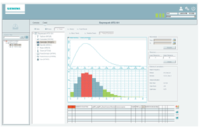
") what you need is some monitoring incorporated into that also measuring various values and graphing it on the app
what you need is some monitoring incorporated into that also measuring various values and graphing it on the app